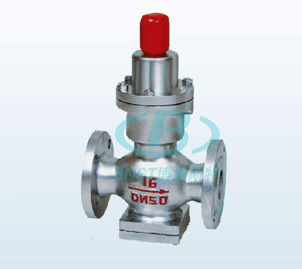
Bellows pressure reducing valve

Bellows pressure reducing valve
Nominal diameter: DN20 ~ 50mm
Nominal: PN0.6 ~ 1.6MPa
Main material: carbon steel, stainless steel
Temperature: ≤200 ℃
Main material: carbon steel, stainless steel
Operation: manual
Flange Standard: GB / T17241.6, GB/T9113
test standard: GB/T13927, API598
Bellows pressure reducing valve use instructions
It is used on the pipeline of steam, air and water non-corrosive medium with temperature below 200 °C, so that the pressure of the medium passing through the valve body is kept constant to meet the needs of work. The inlet pressure P1 of the valve is 1.0-0.1 MPa, the outlet pressure P2 of the bellows pressure reducing valve is 0.4-0.05 MPa, and the pressure difference between the valve before and after the valve is not more than 0.6 MPa, and should not be less than 0.05 MPa.
Principle of use and structure description
1. The inlet medium pressure before the valve enters the body cavity from the opening gap of the valve flap and the valve body sealing ring, so that the medium pressure flows through the combination box of the bellows. The bellows and the spring are compressed by the pressure of the medium, and the valve flap follows the valve stem. Displacement, the valve flap is closed to the sealing ring of the valve body, the medium before the valve is cut off, and the pressure of the medium after the valve is not supplemented. When the pressure of the medium behind the valve is lowered, the bellows is deformed by the radial force of the adjusted spring, and the valve stem is opened by the valve stem. The pressure is reduced after the medium is replenished through the valve body seal.
2. The bellows pressure reducing valve is composed of a valve body, a valve cover, a valve flap, a valve body sealing ring, a valve stem, a bellows, an adjusting spring and the like. The body cavity inlet is assembled with a valve flap, a valve body sealing ring and an auxiliary spring. The auxiliary spring is to maintain the automatic sealing of the valve flap and the valve body sealing ring, and the elastic body sealing member (corrugated pipe) is assembled in the outlet body cavity to ensure the leakage of the medium pressure behind the valve and to compensate for the pressure unevenness. The screw is used to adjust the spring load pressure relief valve performance.
Main dimensions
| Nominal diameter DN | Dimensions | Connection size | |||||||||||||||||
| L | H | H1 | PN1.6MPa | PN1.6MPa | PN1.6MPa | ||||||||||||||
| 0.6/1.0MPa | 1.6MPa | D | K | N-Φ | d | C | D | K | N-Φ | d | C | D | K | N-Φ | d | C | |||
| 15 | 140 | 140 | 290 | 90 | 80 | 55 | 4-12 | 40 | 12 | 95 | 65 | 4-14 | 45 | 12 | 95 | 65 | 4-14 | 45 | 14 |
| 20 | 140 | 140 | 295 | 98 | 90 | 65 | 4-12 | 50 | 12 | 105 | 75 | 4-14 | 55 | 14 | 105 | 75 | 4-14 | 55 | 14 |
| 25 | 160 | 160 | 295 | 110 | 100 | 75 | 4-12 | 60 | 14 | 115 | 85 | 4-14 | 65 | 14 | 115 | 85 | 4-14 | 65 | 14 |
| 32 | 1080 | 180 | 295 | 110 | 120 | 90 | 4-14 | 70 | 14 | 135 | 100 | 4-18 | 78 | 16 | 135 | 100 | 4-18 | 78 | 16 |
| 40 | 200 | 200 | 325 | 125 | 130 | 100 | 4-14 | 80 | 14 | 145 | 110 | 4-18 | 85 | 16 | 145 | 110 | 4-18 | 85 | 16 |
| 50 | 230 | 230 | 325 | 125 | 150 | 110 | 4-14 | 90 | 14 | 160 | 125 | 4-18 | 100 | 16 | 160 | 125 | 4-18 | 100 | 16 |
| 65 | 280 | 325 | 130 | 160 | 130 | 4-14 | 110 | 14 | 180 | 145 | 4-18 | 120 | 18 | 180 | 145 | 4-18 | 120 | 18 | |
| 80 | 310 | 380 | 160 | 185 | 150 | 4-18 | 125 | 16 | 195 | 160 | 4-18 | 135 | 18 | 195 | 160 | 8-18 | 135 | 20 | |
| 100 | 350 | 380 | 170 | 205 | 170 | 4-18 | 145 | 16 | 215 | 180 | 8-18 | 155 | 20 | 215 | 180 | 8-18 | 155 | 20 | |


